To that end, I'm going to share what info I've collected so far, and when I finally end up buying whatever unit I do, I'm going to do a full teardown on it and post the results here.
As another matter, I'll openly post details on who I buy the unit from and impressions after receiving it.
Near as I can tell right now, there appear to be about 4 "factories" that make different units.
One thing I've been asking all of the sellers for (and I would encourage others to do the same) is photos of the actual unit (including PCBs) with a unique identifier in the photo to prove that the unit they say they are going to send me is the actual one they send me. Of course, some sellers immediately bail at this, but then you know who to avoid ahead of time.
In general, a lot of the components used in a C4 are getting quite long in the tooth. Many of the parts are approaching 20 years of age. Thus, you stand a fair risk of getting pulls (used parts) and/or remarked parts on these.
In following posts, I'll provide photos of what I can discern as differences between the units along with some commentary about whatever info I can provide at this point.

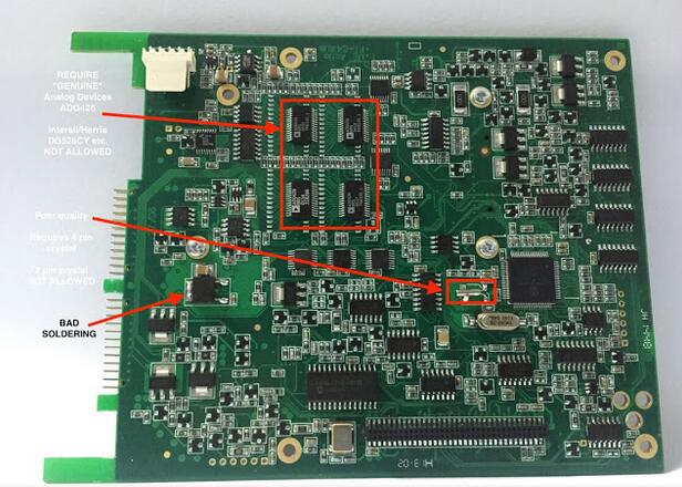
In this first photo, I've outlined some things I feel are important to note. They have a set of 4 analog switches on the PCB. In this photo, they are ADG426 from OBD2TOOL. I've seen some clones that use DG526CY from Harris/Intersil. The DG526CY, besides being completely obsolete, has an typical RDSON of 270 ohms vs 80 for the Analog Devices part. It also has a -55dB isolation vs -75dB for the AD part. In short, the AD part is just a much better mux. So with that said, I would insist on any unit I'm interested in using those.
A second thing you'll notice is the use of can crystals where 4 pin variants were intended. This is just sloppy and cheap. There may also be issue with loading (and ultimately clock stability) depending on whether they matched the loading caps to the substituted crystal or not.
I haven't had a set of photos high res enough to look at the rest of the actives in detail yet, as most sellers don't seem to post them.
There's also an issue pointed out on the bottom of the board where one of the (what appears to be) MOSFETs in (what appears to be a) D2 PAK looks like it was hand soldered. Again, no good.
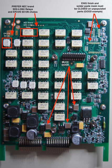
This next photo is of the relay PCB -- I think one of the MHH members posted this from an original SDC4.

You'll notice the use of NEC UD2-4.5NU relays and EPCOS S513N chokes. I've seen plenty of PCBs where they remove the chokes and stub them out with 0 ohm resistors. That is a high crime in terms of signal integrity. You see a lot of "full chips" comments where these are present, although that is a bit of a misnomer. It should read as "common mode filters present".
On this PCB, you'll also notice the use of multilayer ceramic capacitors (MLCC) near the switching supplies. A lot of clones seem to use electrolytic capacitors in place of the bigger MLCCs because of the cost. MLCCs are preferred for switchers because of their low ESR. I really cannot comprehend why the clone makers skimp on these. Even in the US, in reel (e.g. 4K pcs) qty, a 47uF MLCC is about $0.20/ea. That means the difference of probably about $0.50 for the whole PCB. The other advantage of MLCCs is that they more or less last forever, whereas electrolytic caps will eventually dry out and fail (and who knows how old the ones you're getting are and what the quality is to begin with).
In the upper right hand corner, you'll see some footprints that weren't solder pasted during stencil printing. To me, this is a good thing. You know what parts were intended to be populated and which were not. You also get a chance to examine the ENIG finish.
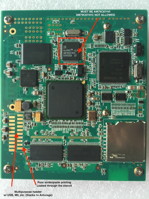
In the next photo, you'll see the MPC5200 board. This is an 8 layer PCB.

There are a couple of things of note on this board:
(1) The AMD 10/100 ethernet PHY that's used comes in 2 revisions and a few different temperature ratings. I have to check the details carefully between the rev A and B, but in terms of temp rating, this should be 'I' (industrial) vs 'C' (commercial).
These PHYs are ancient now, so any price difference should be minimal between the C and I version. Thus, again, I can't imagine why anyone would try to save $0.01 and use the C version.
(2)(Anturage corrected me here -- this header brings out USB, MII (Ethernet MAC), and some other signals)
(Will update below with the location of JTAG when I find it...)
The header at the lower left hand corner of the board is the JTAG header for the MPC5200. For PowerPC, they refer to this interface as BDM. I haven't seen anyone talking about it on here, but this could be quite useful in some cases if/when the SDC is flaking out. For anyone who's not familiar with this interface, it allows you to halt/breakpoint/single step the processor. You can also test the memory attached to the CPU etc. Unfortunately, on this particular PCB, some solder paste leaked through (although I'm not exactly sure how this could happen if I think about it...) onto a few of the pads.
(3) The memory chips are at the bottom. They're DDR SDRAM (I made a mistake when I originally posted this, I wrote that they were not DDR, but upon closer inspection, they are). You can see the series termination resistors between the memory chips and the MPC5200. As others have pointed out, these should be identical and from the same date/lot code. These parts are plentiful and cheap as dirt, so there's absolutely no excuse for any funny business there.
(4) The Spansion S29GL064N is a 64Mb (8MB) parallel NOR flash. Pretty standard for the time this unit was designed. This is what the MPC5200 boots from and where U-Boot, the RTOS, etc. live. You can dump and rewrite the contents of this flash via JTAG (mentioned above). These parts are still readily available and cheap.
You'll notice on this PCB that right below the AMD PHY, there's a 32KHz tuning fork crystal in a 4 pin package. This is the package that should have been used on the other PCB as well.
In general, this particular PCB looks to be of reasonably high quality.
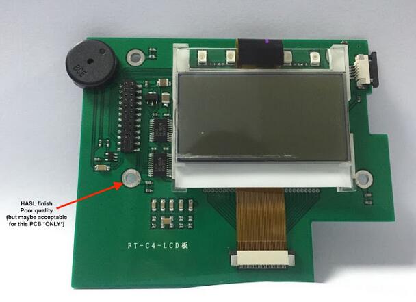
The last photo that I have is of the LCD display.

I've seen a lot of different variants of this particular board.
There's this example 'FT-C4-LCD'. I've seen another 'LCD V1.1' variant as well.
The biggest thing with this board is that it's a HASL (hot air solder level) finish. Granted, this is not the most complex PCB in the world by a long stretch, but it just goes to show you how for these companies will go to save every last penny. Although I haven't seen the back side of one of the 'FT-C4-LCD' variants, the 'LCD v1.1' variant seems to use some ST microcontroller. Maybe the FT-C4-LCD has one on the back?
There's nothing else particularly remarkable about this board, although my impression is that the higher quality units seem to use this FT-C4-LCD variant. If anyone has information to the contrary, I'd certainly appreciate knowing about it.
So as I've mentioned before, I've been sending these photos to any prospective sellers with SD C4 units and asking them to address the issues I've pointed out here in writing.
If they either can't or won't, I just simply move on. I'm sure there are some people that will argue that I'm just wasting my time, but that's fine, it's my time to waste. I think if enough buyers start insisting on better quality up front, and stop buying garbage, it may encourage the factories to improve their quality in general.
To that end, I'm asking any seller to guarantee, in writing, that I will receive exactly what we agreed upon up front, or that they will have to provide a full refund and pay return shipping. To be fair, I am willing to pay more for that. I'm not asking for a top shelf unit at a rock bottom price.
So for any sellers reading this that are interested, please post a note on here, as it may be of interest to others. No need to PM me. Any experience that I have with any seller, I will report back to on here fairly and accurately. I think anyone deserves a fair chance. At the same time, I will be completely honest and detailed about the entire experience, so please bear that in mind ahead of time. I would encourage others to do the same. I feel like this is one place where open communication will benefit everyone.
To any sellers that might be reading this:
Please understand that none of us want to buy a unit, have problems, and have to deal with sending back to China and playing games with you. All anyone wants is a high quality car diagnostic scanner that will work reliably for years. It is better for you and for us to pay a little more up front and get a better quality product. Since you go to great lengths to obscure your production sources, it becomes your job to communicate to them that poor quality is not acceptable.
No comments:
Post a Comment